Solusi Engraving Modern: Cara Cerdas Menciptakan Hasil Presisi
Solusi Engraving Modern: Cara Cerdas Menciptakan Hasil Presisi menjadi pilihan utama bagi banyak pelaku usaha, industri kreatif, hingga perusahaan manufaktur…
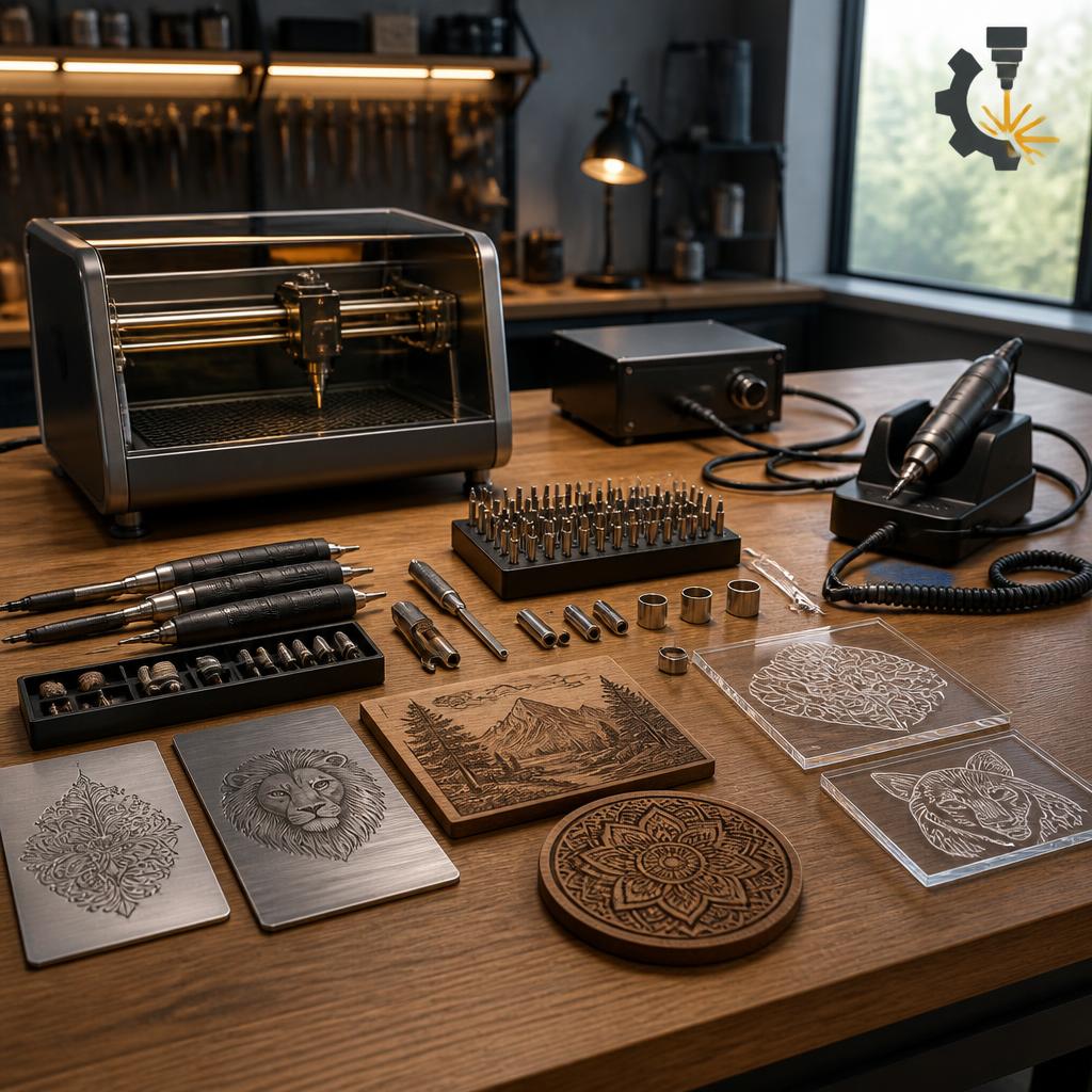
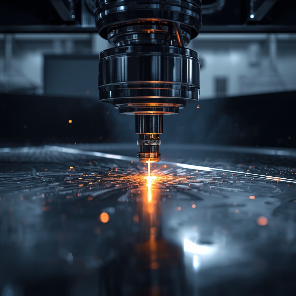
Ukir & Penandaan Laser Presisi
Solusi Engraving Modern: Cara Cerdas Menciptakan Hasil Presisi menjadi pilihan utama bagi banyak pelaku usaha, industri kreatif, hingga perusahaan manufaktur…
engravingsys – Engraving memang sudah menjadi seni dan teknik yang tak lekang oleh waktu. Dalam dunia Produk & Peralatan Engraving,…
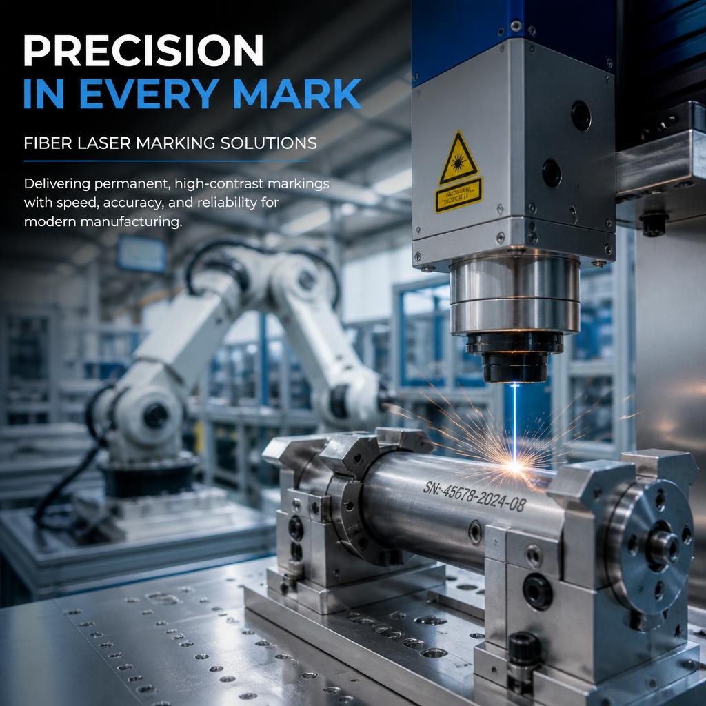
Laser Marking Fiber Kini Jadi Andalan Industri Presisi Modern karena mampu menghadirkan hasil ukiran super detail, cepat, dan tahan lama…
Fakta Menarik Industri Engraving yang Kini Mulai Meledak Rahasia Industri Engraving Modern yang Sering Lolos dari Mata Pebisnis ternyata mulai…
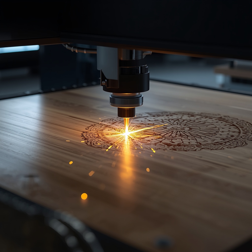
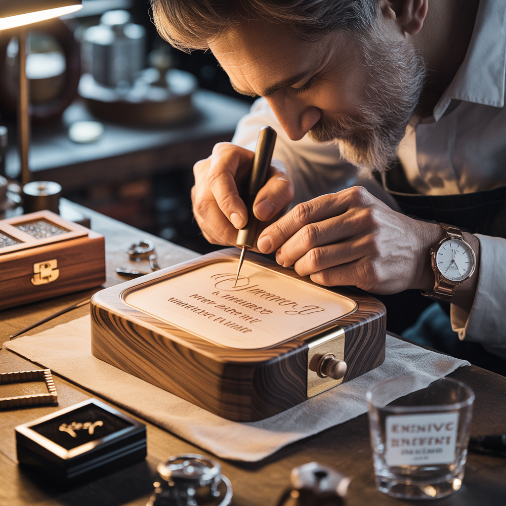
Tips Engraving Kayu agar Detail Lebih Tajam wajib dipahami jika Anda ingin menghasilkan ukiran kayu yang rapi, presisi, dan terlihat…
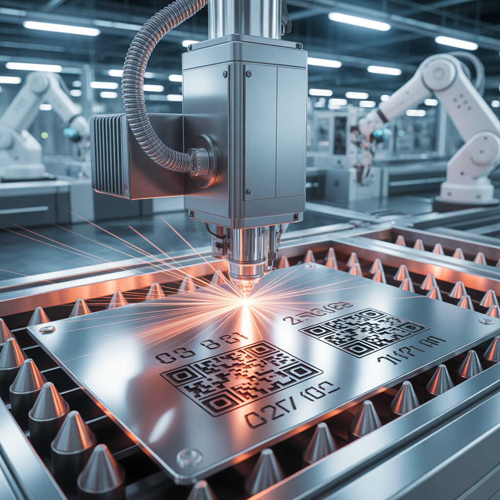
engravingsy – Solusi Engraving Presisi untuk Logam Premium kini menjadi kebutuhan penting bagi banyak industri yang mengutamakan detail, estetika, dan…
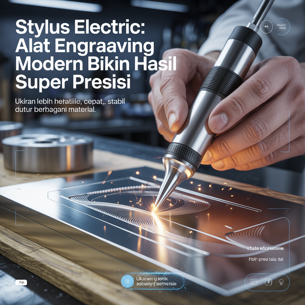
Produk Engraving Stylus Electric semakin populer di kalangan pengrajin, pelaku usaha custom, hingga pecinta DIY yang ingin menghasilkan ukiran rapi…
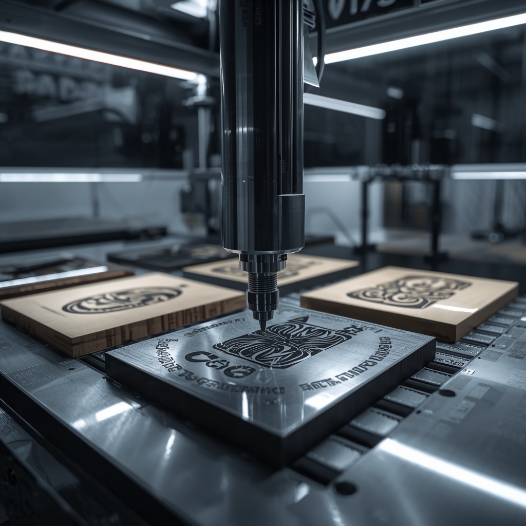
Teknik Engraving Stainless Steel Modern: Rahasia Ukiran Lebih Tajam dan Super Presisi semakin banyak dibahas karena kebutuhan engraving berkualitas terus…
engravingsys.com – Ide Kreatif Engraving: Rahasia Membuat Hadiah Personal Jadi Lebih Bermakna dan Tak Terlupakan adalah solusi modern untuk siapa…
engravingsys.com – Rahasia Efisiensi Produksi: 7 Manfaat Laser Marking untuk Industri Modern yang Jarang Disadari kini menjadi topik yang semakin…